Kee Safety Search
Menu
  • Phone +966-567996637
  • Email [email protected]
Global Locations
  • Export
  • Canada
  • China
  • Danmark
  • Deutschland
  • France
  • India
  • Polska
  • Saudi Arabia
  • Singapore
  • Switzerland
  • United Arab Emirates
  • United Kingdom
  • United States
  • Products
    • Roof Guardrails
      • All Roof Guardrails
      • KeeGuard
      • KeeGuard Topfix
    • Safety Gates
      • All Safety Gates
      • Kee Gate - Safety Gates
      • Pallet Gates
    • Platforms & Walkways
      • All Platforms & Walkways
      • Kee Walk
      • Bespoke Access Platforms
      • Kee Walk Step-Over Platform Kits
      • Aluminium Safety Guardrail Walkway
    • Lifelines & Anchors
      • All Lifelines & Anchors
      • KeeLine
      • Kee Anchor
    • Skylight Fall Protection
      • All Skylight Fall Protection
      • Kee Dome
      • Kee Cover
    • Safety Rails
      • All Safety Rails
      • Kee Klamp
      • Kee Lite
      • Kee Access
      • Kee Mark
    • Beamclamps & Fixings
      • All Beamclamps & Fixings
      • BoxBolt Cavity Fixings
      • BeamClamp Steelwork Fixings
      • BeamClamp Floor Fixings
    • Services
      • All Services
      • Design & Installation
  • Projects
  • Knowledge Centre
    • News & Safety Tips
    • Downloads
    • Videos
    • Roof Edge Protection
    • Fall Protection
    • General Compliance
  • About
    • Overview
    • History
  • Contact

Products / Kee Klamp

Catalogues

  • Fall Protection Solutions

  • Safety Components Catalogue

  • Safe Steelwork Connections

  • Overview
  • Technical Details
  • Installations
  • Catalogue Items

Documents

Brochures

  • Kee Klamp Fittings Guide (for Middle East)
  • Kee Klamp Fittings Guide (for India)
  • Kee Klamp - Sales Brochure
  • Kee Klamp - Slope Fittings Sales Brochure

Certifications

  • TÜV Certificate

Kee Klamp® Tubular Fittings

A Cost Effective Alternative to Welding with Unlimited Applications

Since 1934, Kee Safety Ltd has been dedicated to providing the world with a versatile, economical, and durable method of building tubular structures. KEE KLAMP tubular fittings are available in more countries, more styles, more sizes, and more colours than any other brand of tubular fitting.

Galvanised Steel Components

Steel tube is an inherently efficient structural component. It is strong, has no sharp corners, and is readily available. The difficulty in using steel tube to form structures arises when joining. Threaded tube must be supplied in set lengths making for zero flexibility in installation. Welding is labour intensive, requires a highly skilled workforce, and specialised equipment.

The answer is KEE KLAMP fittings. The underlying principle is simple but highly effective: use slip-on components to create versatile and rigit tubular structures.

Features  & Benefits of the KEE KLAMP Handrail

  • Made of galvanised cast iron to BS EN ISO 1461
  • High corrosion resistance
  • Quick installation
  • No welding, so no hot work permits required
  • No threading or bolting, so no special tools required
  • A flexible system that can accommodate on site variations
  • Cost effective to install as it is quick to install and only low skilled workforce is required
  • TUV certified for strength, manufacturing quality and consistency

The Kee Klamp® Fitting

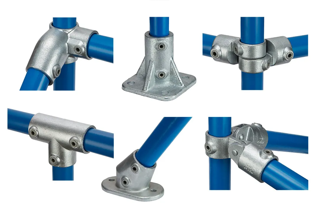
The engineering principle behind the KEE KLAMP fitting is the foundation of the most versatile tube connection system available. There are many variations of tubular fittings to suit a wide range of applications, providing the versatility to achieve any structural configuration.

KEE KLAMP tubular fittings are galvanised iron castings manufactured to the requirements of BS EN 1562 & 1563. We have engineered a range of fittings to suit different tube sizes, from 17.5mm to 60.3mm. Hexagon socket set screws firmly lock the fitting to the tube. Set screws are manufactured in case hardened steel and are protected against corrosion with KEE KOAT; alternatively, stainless steel screws are available.

A KEE KLAMP fitting (size 5 to 9) can support an axial load of 2000 lbs (900 kg). per grub screw with the grub screw tightened to a torque of 29 lbs. ft.(39 Nm); rating includes a safety factor of 2:1.

New Kee Klamp Slope Fittings

We have expanded our KEE KLAMP fittings range and introduced 12 new fittings. The new KEE KLAMP fittings have been designed for installation on steeper gradients, they offer builders and specifiers an aesthetically pleasing option.

The new KEE KLAMP slope fittings have been designed to enhance the building of guardrail along staircases and ramps, particularly when the slope is greater than 30 degrees. The new range introduces single fittings to cater for situations where currently a combination of fittings is required. Not only does this improve the aesthetics of the finished guardrail but it also allows for a quicker and easier installation.

New KEE KLAMP slope fittings are available in two sizes: size 7 (outside diameter 42.4mm) and size 8 (outside diameter 48.3mm).

To learn more about our new KEE KLAMP fittings please download the new KEE KLAMP Slope Fittings brochure.

Affordable

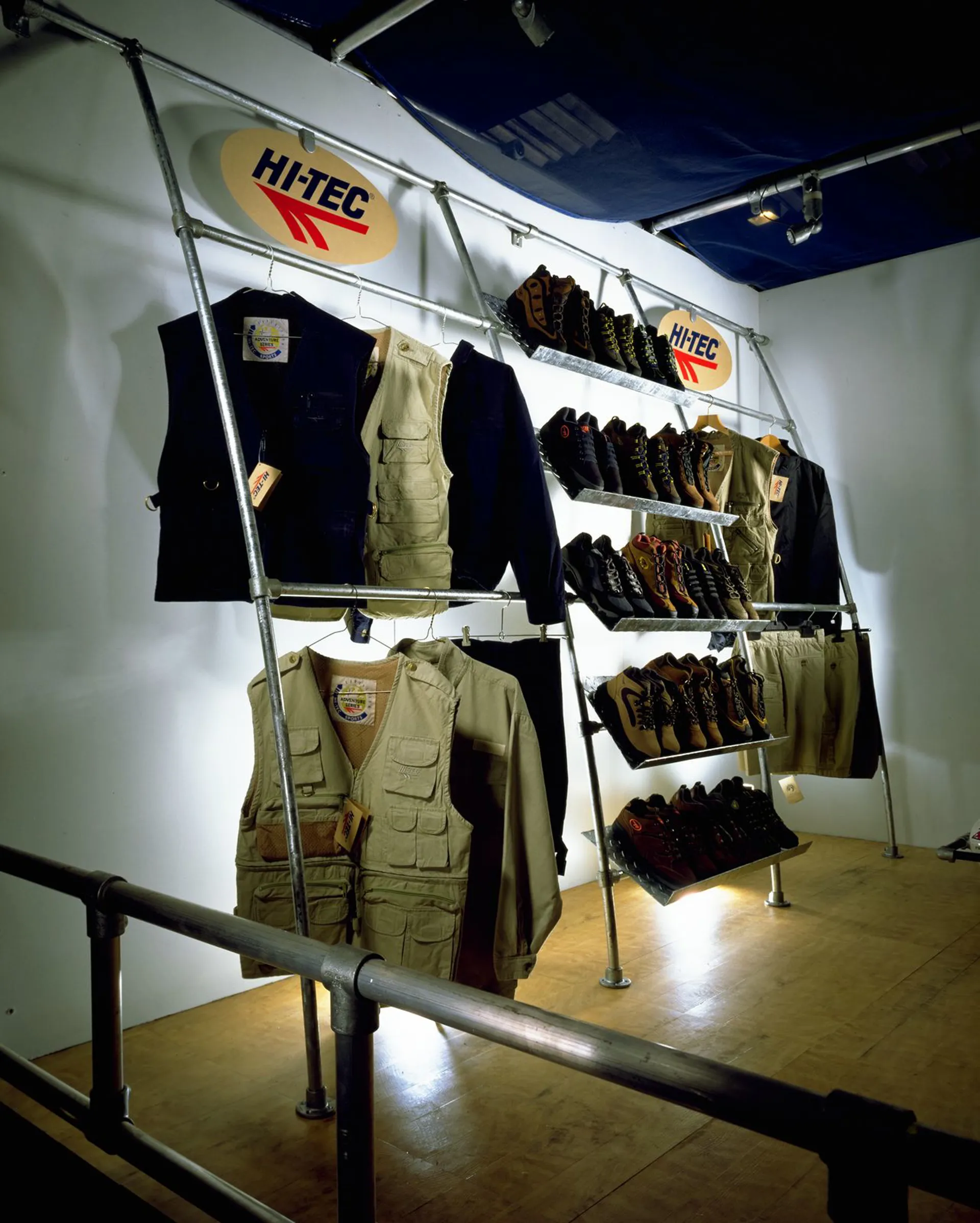
Fabricating and building with KEE KLAMP tubular fittings saves time, money, and resources.

View our featured solutions below to learn more about how KEE KLAMP products can help bring your projects in on time, and under budget! Contact us today with your application for a free quote.

Kee Klamp® Technical Specifications

The KEE KLAMP Tubular Fittings

The simple but effective engineering principle of the KEE KLAMP tubular fittings is the foundation of the most versatile tube connection system available. There are many variations of tubular fittings to suit wide-ranging applications, providing the versatility to achieve virtually any structural configuration.

KEE KLAMP tubular fittings are generally made from cast iron* and are manufactured to the requirements of EN 1562 & EN 1563 and galvanized to the requirements of EN ISO 1461. A range of Components to suit seven sizes of tube is available. A simple hexagon key is the only tool required to create a strong, rigid joint. A recessed grub screw tightened by the hexagon key, firmly locks the tube into the Component. The grub screw is generally manufactured in case hardened steel* and benefits from Kee Koat® protection against corrosion. This combined with the ThredKoat® (patented) factory applied coating for the threaded recesses ensures that KEE KLAMP tubular fittings achieve longer life and better corrosion resistance.

A KEE KLAMP Component (size 5 to 9) can support an axial load of *900 Kg (2000 lbs) per grub screw with the grub screw tightened to a torque of 39 Nm (29 lbs. ft.).

* Materials used can vary according to application. Please refer to manufacturer for detailed specification.

Specifying KEE KLAMP Tubular Fittings

The information on tubular fittings in this site is comprehensive, and because of the coding system we have adopted, easy to use.

Diagrams are shown for each Component showing entry of tube, a table of dimensions and a definition of use adjacent to its appropriate Type number (10, 15, 20, 25 etc.).

Alongside the Type number is a code (4, 5, 6, 7, etc.) relating to the outside diameter of the tube for which the Kee Klamp tubular fitting had been designed. The relationship between the KEE KLAMP tube reference and standard tube outside diameter is explained in the aforementioned chart.


KEE KLAMP
tube size
Tube diameter
(mm o.d.)
Nominal bore*
(mm)
3 17.5 10
4 21.3 15
5 26.9 20
6 33.7 25
7 42.4 32
8 48.3 40
9 60.3 50

*Nominal bore is an arbitrary dimension, because the bore varies with the wall thickness of the tube.

Example: (1) A 10-7 is a Type 10 KEE KLAMP Component with both sockets designed to accept a tube that has an outside diameter of 42.4mm or 1 11/16" (1 1/4" Nominal tube Size). (2) A 25-9 is a Type 25 KEE KLAMP Component with all three sockets designed to accept a tube that has an outside diameter of 60.9mm or 2 3/8" (2" N.P.S.).

Where more than one tube reference is shown alongside a particular Type number, it indicates that the individual sockets are designed to accept different sizes of tube. In a multi-digit code number the first figure relates to the 'A' socket and the second to the 'B' socket. Example (3) A 45-76 is a Type 45 KEE KLAMP Component with 'A' socket accepting a tube that has an outside diameter of 42.4mm or 1 11/16", and a 'B' socket accepting a tube/pipe that has an outside diameter of 33.7mm or 1 11/32".

While Kee Klamp Ltd. can give a general guidance relating to the use of each KEE KLAMP Component detailed in this site, the nature of the product means that the ultimate responsibility for selecting the correct fitting for an application must lie with the customer.

The customer should also ensure that the existing structure to which the KEE KLAMP construction is being secured, is of sufficient strength to support both the self weight of the KEE KLAMP construction and the imposed loads applied, including wind loads, snow loads, and any other superimposed loads.

Metric Beam Load Table

For uneven load distributions or single spans, the required tube size must be determined by standard bending moment calculations assuming a KEE KLAMP joint to give a simply supported beam. The table shown below gives an indication only of the safe load uniformly distributed, in kg, that may be carried per shelf consisting of front and back tubes when used as continuous beams. Recommended set screw torque: 39 Nm.

At loads greater than 900 kg, consideration must be given to grub screw slip.


Table reflects a safety factor of 1.67:1

Metric Upright Load Table

This table gives an indication only of the safe load, in kg., that may be carried between the above restraints by single tubes to EN 10255 when used as uprights. Loads listed under 'A' columns refer to those loads that are obtainable according to schematic 'A', and loads listed under 'B' columns refer to those loads that are obtainable according to schematic 'B'. Schematic 'B' details a racking system that is mechanically affixed to the surface on which it stands whereas schematic 'A' details a free-standing racking system. Recommended set screw torque: 39 Nm

Load table (Kg) - unfixed upright

Table reflects a safety factor of 2:1

Load table (Kg) - fixed uprights

Table reflects a safety factor of 2:1

Vibration Test Report

TEST REPORT: Vibration of KEE KLAMP Assemblies

Exhaustive tests on samples of standard size 7 KEE KLAMP Tubular Fittings were performed by an independent research laboratory. The purpose of the test was to evaluate the use of either standard set-screws or self-locking set screws.

Test Arrangement

A "Tee" section test assembly was made using three 300mm lengths of galvanized 1 ¼" standard pipe held together by a socket Tee Component (Type 25-7). The vertical leg of the test assembly was supported in a standard railing flange (Type 62-7). The completed assembly was then rigidly attached to the vibration table.

The test assembly was initially assembled using standard grub screws and tested in the configuration. The standard grub screws were then replaced with self-locking grub screws and the tests repeated.

Test Procedure

The test was conducted on a Ling 667 Kg Electromagnetic vibration table.

The table was programmed to perform a resonance search between 25 and 350 Hz. The following table details the resonant frequencies that were recorded.

During the resonance search amplification factors, Q, were measured at each resonant frequency, the point of reference being the end of one horizontal pipe. The table was then held at one of the resonant frequencies, set in motion with a controlled acceleration level of 4g, and run for a period of six hours. This was repeated for three more resonant frequencies in descending order of "Q" factor.

During the twenty-four hours of vibration at the four resonant frequencies above no signs of loosening with either type of set screw occurred.

Guardrail for loading bays at a logistics company

+
Bespoke access platforms for Dubai Air Navigation Services

Bespoke Access Platforms for Dubai Air Navigation Services

+

General Questions

Installation Questions

Technical Questions

Catalogue Items

  • Single Socket Tee

    10

    Single Socket Tee

  • Split Single Socket Tee

    A10

    Split Single Socket Tee

  • 45° Single Socket Tee,

    12

    45° Single Socket Tee,

  • Split 45° Single Socket Tee, 48.3mm O/D

    A12

    Split 45° Single Socket Tee, 48.3mm O/D

  • Straight Coupling

    14

    Straight Coupling

  • 90° Elbow

    15

    90° Elbow

  • Clamp-on Tee

    16

    Clamp-on Tee

  • Clamp-on Crossover

    17

    Clamp-on Crossover

  • Internal Coupling

    18

    Internal Coupling

  • Adjustable Side Outlet Tee

    19

    Adjustable Side Outlet Tee

  • Side Outlet Elbow

    20

    Side Outlet Elbow

  • 90° Side Outlet Tee

    21

    90° Side Outlet Tee

  • Split Two Socket Cross / 90°Side Outlet Tee

    A21/26

    Split Two Socket Cross / 90°Side Outlet Tee

  • Three Socket Tee

    25

    Three Socket Tee

  • Two Socket Cross

    26

    Two Socket Cross

  • 30° to 60° Single Socket Tee

    29

    30° to 60° Single Socket Tee

  • 30° to 45° Adjustable Cross

    30

    30° to 45° Adjustable Cross

  • Pallet Flange

    31

    Pallet Flange

  • Three Socket Cross

    35

    Three Socket Cross

  • Split Three Socket Cross

    A35

    Split Three Socket Cross

  • Four Socket Cross

    40

    Four Socket Cross

  • Split Four Socket Cross

    A40

    Split Four Socket Cross

  • Crossover

    45

    Crossover

  • Split Crossover

    A45

    Split Crossover

  • Combination Socket Tee & Crossover

    46

    Combination Socket Tee & Crossover

  • Single Swivel Socket

    C50

    Single Swivel Socket

  • Female Single Swivel Socket Member

    F50

    Female Single Swivel Socket Member

  • Male Single Swivel Socket Member

    M50

    Male Single Swivel Socket Member

  • Male Single Swivel Socket Member

    MH50

    Male Single Swivel Socket Member

  • Modified M50-8 with Offset Slot

    P50

    Modified M50-8 with Offset Slot

  • Double Swivel Socket

    C51

    Double Swivel Socket

  • Male Double Swivel Socket Member

    M51

    Male Double Swivel Socket Member

  • Male Double Horizontal Swivel Socket Member

    MH51

    Male Double Horizontal Swivel Socket Member

  • Modified M51-8 with Offset Slots

    P51

    Modified M51-8 with Offset Slots

  • Corner Swivel Socket

    C52

    Corner Swivel Socket

  • Male Corner Swivel Socket Member

    M52

    Male Corner Swivel Socket Member

  • Swivel Elbow

    BC53

    Swivel Elbow

  • Adjustable Three Way Swivel Socket

    C53

    Adjustable Three Way Swivel Socket

  • Variable Angle Double Swivel Socket Member

    M53

    Variable Angle Double Swivel Socket Member

  • Obtuse Angle Elbow

    55

    Obtuse Angle Elbow

  • Variable Elbow, 11º to 30º

    55A

    Variable Elbow, 11º to 30º

  • Acute Angle Elbow 30º to 45º

    56

    Acute Angle Elbow 30º to 45º

  • Acute Angle Elbow, 11º to 30º

    56A

    Acute Angle Elbow, 11º to 30º

  • Modified M50-8 with Slot

    P57

    Modified M50-8 with Slot

  • Modified P57

    P57E

    Modified P57

  • Swivel Flange

    C58

    Swivel Flange

  • Swivel Flange Plate

    M58

    Swivel Flange Plate

  • Double Central Flange Fitting

    P58

    Double Central Flange Fitting

  • Spigot Flange

    59

    Spigot Flange

  • Extra Heavy Flange

    60

    Extra Heavy Flange

  • Flange

    61

    Flange

  • Standard Railing Flange

    62

    Standard Railing Flange

  • Angle Base Flange

    63

    Angle Base Flange

  • Standard Vertical Railing Base

    64

    Standard Vertical Railing Base

  • Standard Horizontal Railing Base

    65

    Standard Horizontal Railing Base

  • Ground Socket

    66

    Ground Socket

  • Angle Flange

    67

    Angle Flange

  • Wall Flange

    68

    Wall Flange

  • Rail Flange with Toeboard Adaptor, 42.4mm O/D

    69

    Rail Flange with Toeboard Adaptor, 42.4mm O/D

  • Rail Support

    70

    Rail Support

  • Weather Cap

    71

    Weather Cap

  • Stair Tread Support

    72

    Stair Tread Support

  • Collar

    75

    Collar

  • Hook

    76

    Hook

  • Plastic Plug

    77

    Plastic Plug

  • Eye Fitting

    78

    Eye Fitting

  • Sheeting Clip

    79

    Sheeting Clip

  • Single Sided Clip

    81

    Single Sided Clip

  • Double Sided Clip

    82

    Double Sided Clip

  • Pin Fitting

    83

    Pin Fitting

  • Malleable Plug

    84

    Malleable Plug

  • Angle Tee

    86

    Angle Tee

  • Angle Elbow

    87

    Angle Elbow

  • Three Socket Angle Tee

    88

    Three Socket Angle Tee

  • Two Socket Angle Cross

    89

    Two Socket Angle Cross

  • PGR Three Socket Tee

    90

    PGR Three Socket Tee

  • PGR Two Socket Cross

    91

    PGR Two Socket Cross

  • PGR Elbow

    92

    PGR Elbow

  • PGR Tee

    93

    PGR Tee

  • PGR Internal Spigot

    95

    PGR Internal Spigot

  • Set Screws

    97

    Set Screws

  • Anti-theft Device

    97ATD

    Anti-theft Device

  • Ratchet Set

    98

    Ratchet Set

  • Hex Key

    99

    Hex Key

  • Plastic Set Screw Cap

    100

    Plastic Set Screw Cap

  • Sheeting Clip without Hardware

    105

    Sheeting Clip without Hardware

  • Swivel Tee

    114

    Swivel Tee

  • Horizontal Railing Base

    115

    Horizontal Railing Base

  • Packer Plate for Type 115

    S115

    Packer Plate for Type 115

  • Cover Flange

    118

    Cover Flange

  • Corner Crossover

    121

    Corner Crossover

  • Crossover Coupling

    145

    Crossover Coupling

  • Round Base Flange

    262

    Round Base Flange

  • Offset Rail Wall Flange

    265

    Offset Rail Wall Flange

  • Parapet Flange

    316

    Parapet Flange

  • Left Hand Level to Sloping Down Side Outlet Elbow, 30º to 45º

    320LH

    Left Hand Level to Sloping Down Side Outlet Elbow, 30º to 45º

  • Right Hand Level to Sloping Down Side Outlet Elbow, 30º to 45º

    320RH

    Right Hand Level to Sloping Down Side Outlet Elbow, 30º to 45º

  • Left Hand Level to Sloping Down Side Outlet Tee, 30º to 45º

    321LH

    Left Hand Level to Sloping Down Side Outlet Tee, 30º to 45º

  • Right Hand Level to Sloping Down Side Outlet Tee, 30º to 45º

    321RH

    Right Hand Level to Sloping Down Side Outlet Tee, 30º to 45º

  • Level to Sloping Down Tee, 30º to 45º

    325

    Level to Sloping Down Tee, 30º to 45º

  • Level to Sloping Up Tee, 30º to 45º

    325A

    Level to Sloping Up Tee, 30º to 45º

  • Level to Sloping Down or Up Cross, 30º to 45º

    326

    Level to Sloping Down or Up Cross, 30º to 45º

  • Three Socket 11°–30°Tee

    327

    Three Socket 11°–30°Tee

  • Two Socket 11°–30°Cross

    328

    Two Socket 11°–30°Cross

  • Single Socket Tee, 11º to 30º

    329

    Single Socket Tee, 11º to 30º

  • Eaves Fitting

    350

    Eaves Fitting

  • Ridge Fitting

    351

    Ridge Fitting

  • 11°–30°Angle Base Flange

    363

    11°–30°Angle Base Flange

  • Three Socket Tee, 30º to 45º

    427

    Three Socket Tee, 30º to 45º

×
  • Products
    • Roof Guardrails
      • All Roof Guardrails
      • KeeGuard
      • KeeGuard Topfix
    • Safety Gates
      • All Safety Gates
      • Kee Gate - Safety Gates
      • Pallet Gates
    • Platforms & Walkways
      • All Platforms & Walkways
      • Kee Walk
      • Bespoke Access Platforms
      • Kee Walk Step-Over Platform Kits
      • Aluminium Safety Guardrail Walkway
    • Lifelines & Anchors
      • All Lifelines & Anchors
      • KeeLine
      • Kee Anchor
    • Skylight Fall Protection
      • All Skylight Fall Protection
      • Kee Dome
      • Kee Cover
    • Safety Rails
      • All Safety Rails
      • Kee Klamp
      • Kee Lite
      • Kee Access
      • Kee Mark
    • Beamclamps & Fixings
      • All Beamclamps & Fixings
      • BoxBolt Cavity Fixings
      • BeamClamp Steelwork Fixings
      • BeamClamp Floor Fixings
    • Services
      • All Services
      • Design & Installation
  • Projects
  • Knowledge Centre
    • News & Safety Tips
    • Downloads
    • Videos
    • Roof Edge Protection
    • Fall Protection
    • General Compliance
  • About
    • Overview
    • History
  • Contact
  • +966-567996637
  • [email protected]

Contact Details

  • P.O.Box: 10374 Jeddah 21433, Kingdom Of Saudi Arabia
  • +966-567996637
  • Contact Us

Latest News

  • Kee Mark as a Social Distancing Solution

    Kee Mark as a Social Distancing Solution

  • Safety Gates or Chains for Safe Access

    Safety Gates or Chains for Safe Access

  • Kee Safety supports IOGP life-saving rules

    Kee Safety supports IOGP life-saving rules

Product Categories

Roof Guardrails Safety Gates Platforms & Walkways Lifelines & Anchors Skylight Fall Protection Safety Rails Beamclamps & Fixings Services

Site Pages

  • Products
  • Projects
  • Knowledge Centre
  • About
  • Ethical Policy
© 1997–2021 Kee Safety, LLC. All Rights Reserved • Privacy Policy